
Charles Keen
Boiler, Engine, Steamliner No. 2 Engine Parts, and New Boiler
| Charles Keen, Madison, Wisconsin made three of these boilers patterned after the Doble “F” boiler, as they have the helical coil water wall. Abner Doble’s notebooks mention working with Keen from June 1948 to February 1950. This was probably while Doble was working for Nordberg in Milwaukee. This boiler has a home made 9 gph fuel oil burner and a quartz rod controller. Keen made three of these. One was installed in Keen Steamliner No.1 and is now in England. One was installed in Keen Steamliner No. 2 and is in my possession. The third boiler was installed in Ron Ziesemer’s Stanley and his son Art sold it to me to be replaced by an authentic Stanley boiler. | 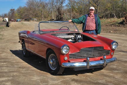 |
|
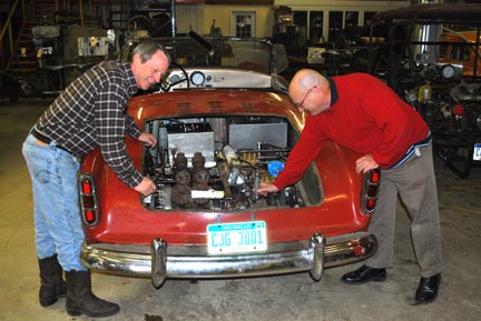
November 2011-Tom Kimmel with his Keen Steamliner No. 2 ready to take a spin. |
||
 |
||
|
Above: 2006-the Keen Steamliner #2 displayed for the September, Chicagoland Chapter, SACA Meets. |
 |
 |
 |
 |
|
 |
 |
|
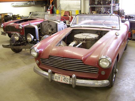
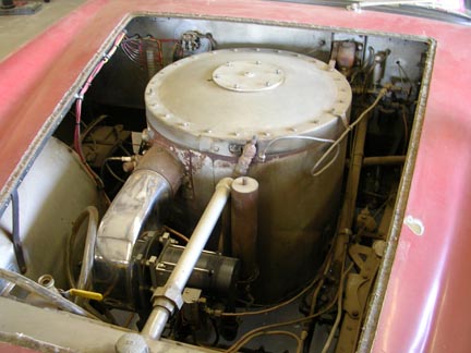
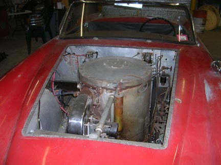
| Boiler in the Car |
 |
 |
|
 |
 |
|
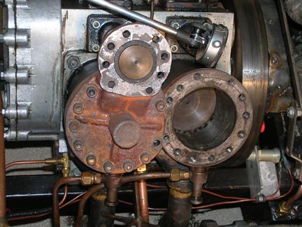
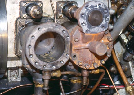
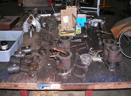
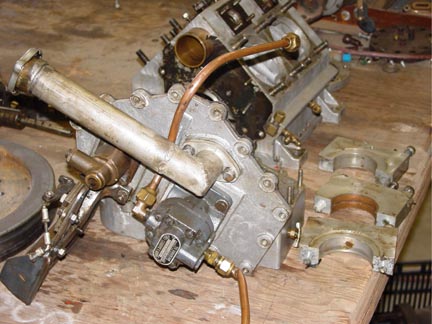
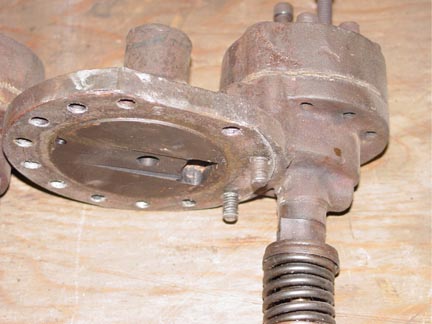
| The engine is 100 cubic inches and is reported to make 130 or 140 horsepower. It is a single acting trunk piston uniflow. Because the exhaust ports are only on one side of the cylinder there may be some breathing problems. | ||
 |
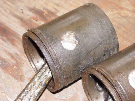
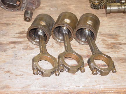
The design is very clever with the intake poppet valve offset the width of the big end of the connecting rod. This is so two connecting rods can be mounted on one crank throw and the cam followers are in line, meaning that one cam operates two valves, albeit 90 degrees apart, at the same time. There is a small cylinder screwed into the head. We do not know what it does, or did originally, however it is a clever idea. This gives extra clearance volume when going slow and at speed the small opening effectively stops the flow of steam thereby decreasing the clearance volume. The auxiliary exhaust valves are the mostclever design and difficult to describe. Let me just say they are small poppet valves actuated by the Johnson bar when it | |
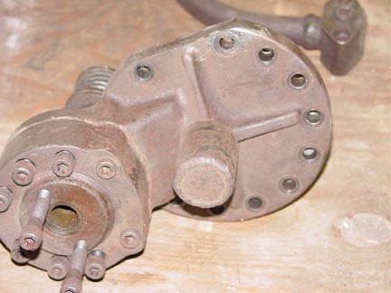
| the flow of steam thereby decreasing the clearance volume. The auxiliary exhaust valves are the mostclever design and difficult to describe. Let me just say they are small poppet valves actuated by the Johnson bar when it shifts the cam into full cutoff for forward and reverse. This way the auxiliary exhaust valves do not require their own sliding camshaft as is done in the Williams engine. The connecting rods were beefed up by adding reinforcing welding beads to the rods, filling in the “H” cross section of them. | 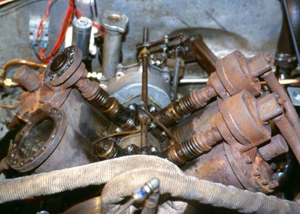 |
|
 |
||
 |
 |
 |
 |
|
 |
 |
|
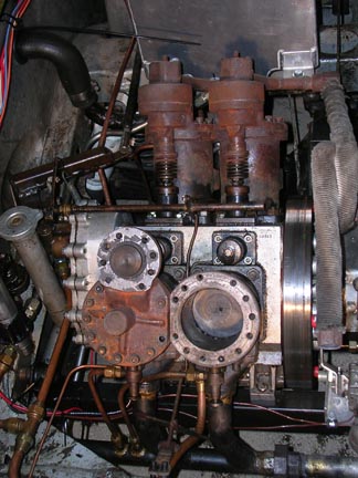
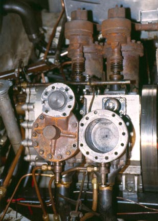
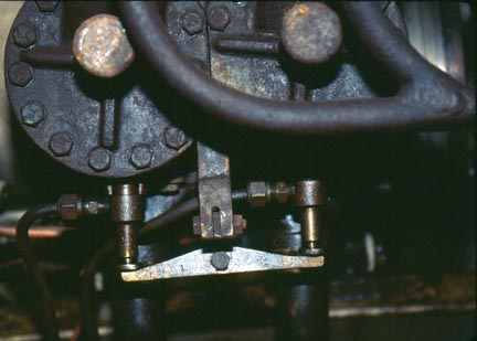
| The Throttle |
 |
|||
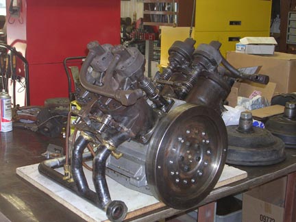
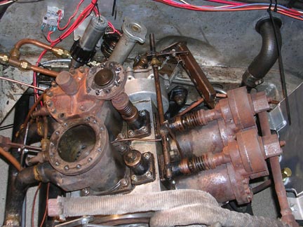
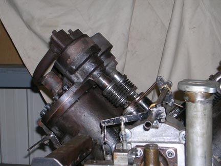
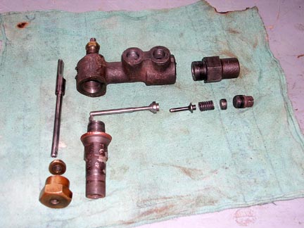
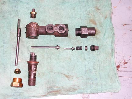
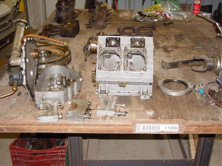
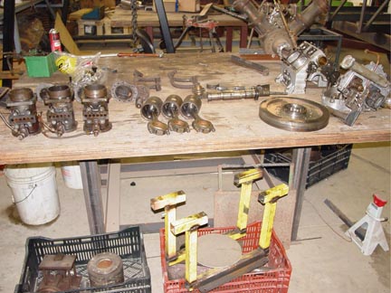
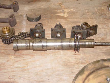
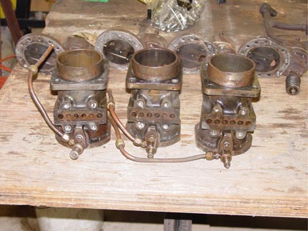
Keen Steamliner #2 Engine (Disassembled View) |
||
| The Keen Steamliner #2 engine is disassembled to show the sliding cam shaft and the center section of a small block Ford 272 engine. By using a flat crank and a 90 degree V design a single acting steam engine is self starting. By using a 90 degree V there only has to be half as many cam grinds on the cam shaft because each cam is actuating two opposed poppet valves. This was a very clever and high speed engine design. It also used only one cylinder casting design. | 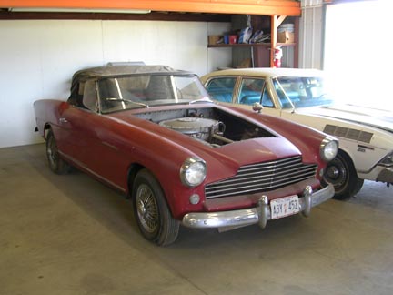 |
|
 |
 |
|
 |
 |
 |
 |
|
 |
 |
|
 |
 |
||
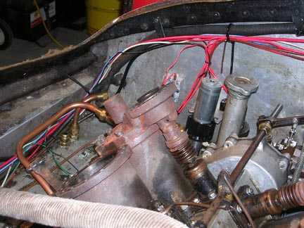
| We have added an electric pump to get oil pressure before engine rotation. Also an oil/water separator column. | |||
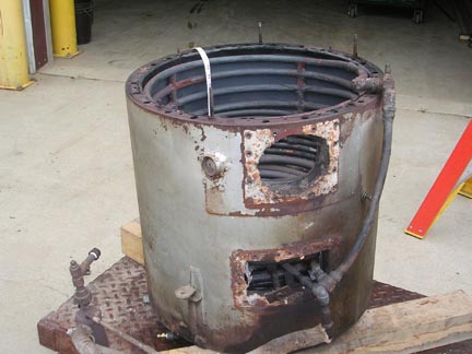
New Boiler |
||
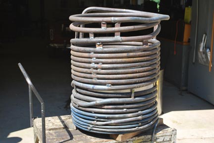
New Keen Steamliner #2 boiler wound in my shop. The first boiler was designed by Doble for Charlie Keen. It had an 8-10 gallon per hour kerosene gun burner and was unmercifully abused by me for several years. Most of the abuse came from not discovering the well hidden valve that kept water from flowing from the water pumps to the boiler. Finally a tube burst. Instead of fixing the tube the decision was made to completely make a new one because of scaling on much of the other tubing. |
 |
|
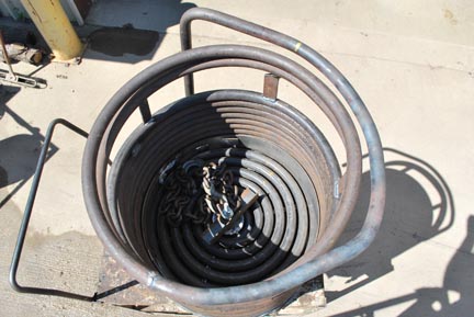 |
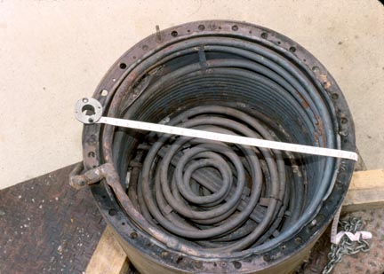
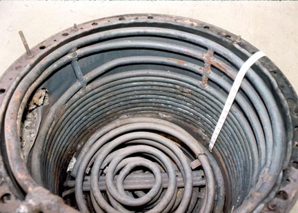
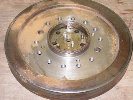
View down past the water wall. Hoisting chain is laying on the top pancake coil. | |
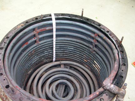
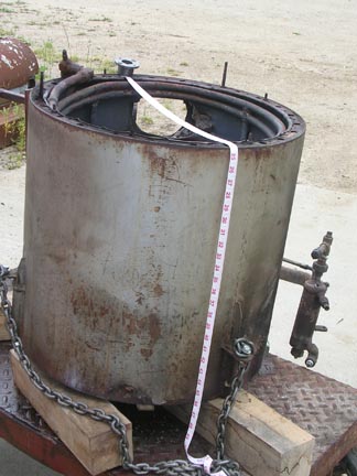
| Heavier thicker walled tubing was used for this replacement boiler than the original. This is all schedule 80 black iron; ¼”, 3/8”, and ½” as it goes up. Shown are the welded transitions between sizes. Each pancake coil was individually wound and then welded at the inside and outside of the coils to the next one. We now have perfected the method of winding two pancake coils pre-welded so that we do not have to make the center weld after they are wound. | 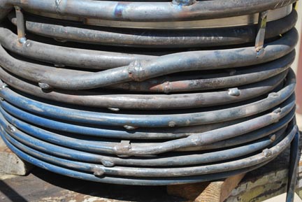 |
|
 |
 |
||||
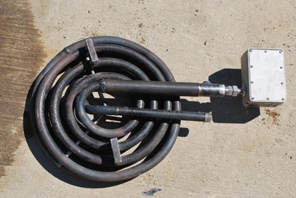
| Superheater made from schedule 160 tubing. We think that Doble originally used very thick-walled superheater tubing to act as a heat sink to even out the steam temperature and to prevent superheater burn out. Modern Burling Instruments quart rod controller with a 13” ceramic tube replacing the quartz rod. |
|
||||
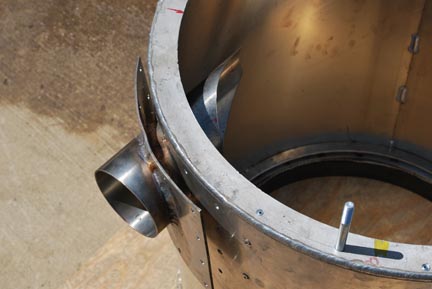 |
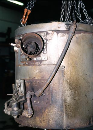
Detail of 4” diameter gun burner inlet. The tubes are bent to make room for this in the water wall. | |
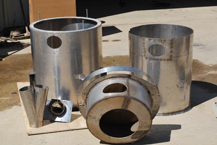
| Exploded view of all the components of the new Keen Steamliner #2 replacement boiler. So far we are working on getting an 8-10 gph burner to work. Beckett makes only a 6 gph as their largest 12 volt burner gun. Keen’s original burner had a military surplus 24 volt motor driven squirrel cage blower fan and it drew too much current and did not have the Beckett’s flame swirl fins. Thus volatiles were formed that burned the eyes in an enclosed space. We are working on how to get two burners to work at the same time. The squirrel cage fans do not produce enough pressure. | 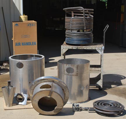 |
||
| Link to Keen Steamliner #1 |