Advanced Uniflow Engine - Guy Immega


  Guy Immega's Advanced Uniflow Steam Engine


Working model  

An Advanced Uniflow Steam Engine has been built to overcome some of the limitations of traditional steam engines. In the history of the steam engine, development was prematurely stopped after the introduction of the more efficient diesel engine and steam turbine in the early 1900s. A uniflow steam engine is an alternative to the more common compound steam engine.

The Advanced Uniflow Steam Engine has increased efficiency, no valve gear, no lubricating oil mixed with the steam, no vacuum condenser, and electronic control of power and speed. Modern materials, manufacturing techniques, and electromechanical valve actuation make these advances possible.
     
(Note: Click on a picture to see a larger view and then use your browser to enlarge it further.)
     

Contents

1.    History

2.    Description

      2.1 Design Objectives

      2.2 Engine Operation

      2.3 Major Components

      2.4 Intake and Exhaust Valves

      2.5 Electronic Controls

3.    Design Details

      3.1 Constant Diameter Cylinder & Piston

      3.2 No Lubrication

      3.3 Test Results

      3.4 Scalability

4.    References

5.    External links


Back to Top

History:

Carnot's theorem (thermodynamics) established the theoretical limit to Rankine cycle heat engine efficiency in 1824; hotter input temperatures increase efficiency. Typical steam engines operate at 10% to 25% efficiency. To maximize efficiency, steam engines are designed to discharge the steam at the lowest possible temperature and pressure – about 100 degrees C and at atmospheric pressure (unless a vacuum condenser is used). In a conventional steam engine, the steam enters and is discharged through the same valve. This creates two problems. The first is that discharged steam needs a large port, which requires significant energy to operate against the pressure of the intake steam. The second problem is that discharged steam cools the intake valve and steam passages, leading to a significant energy loss.

The first of these problems was addressed in 1804 by the compound steam engine, expanding the steam in stages through several cylinders, each cylinder having larger diameter and larger ports. Both problems were addressed in 1827 by the uniflow steam engine in which the steam enters the cylinder via a small high pressure port and leaves the cylinder by a large port in the cylinder wall, uncovered by the piston towards the end of its stroke. The inlet port always stays hot while the exhaust port remains at approximately 100 degrees C. The uniflow engine was popularized by in the early 1900s (Stumpf, Johann 1905). Unfortunately this was also a time when interest in reciprocating steam engines was falling rapidly, since the recently invented (1893) diesel engine achieved efficiencies of about 40%, which is much higher than any reciprocating steam engine can achieve even today (however steam turbines can).

Even with the uniflow engine, several problems remain. If oil is added to the steam to lubricate the piston, it later forms a solid layer inside the boiler that reduces heat transfer. Another problem is poor sealing of the piston in the cylinder over a wide temperature range along the length of the cylinder. Finally, the complex mechanical linkage of the intake valve gear consumes significant power due to frictional losses and steam leaks (Cozby 2012). Some of the intake valve problems were addresses by uniflow engines with piston operated valves (Curtis 1901; Divine 1975; Harvey 1968; Kaneff 1979). The most advanced steam engine design (Sturtevant 1968) had electric control of steam cutoff but did not have a simple solution to allow the steam cutoff to be reduced to zero, or a method to keep the electromagnet from being overheated by the steam. All these problems are addressed in the Advanced Uniflow Steam Engine, developed by Dan Gelbart in Vancouver, BC, Canada in 2010.


Back to Top

Description:

Design Objectives:

  1. No Valve Gear – Eliminate camshaft, steam leaks and mechanical losses.
  2. Electromechanical Intake Valve – Electronic control of steam cutoff (steam engine).
  3. Zero minimum cutoff – Minimize steam consumption at very light loads.
  4. Elimination of Spent Steam – No vacuum condenser (surface condenser) is needed to purge used steam from the cylinder.
  5. No Lubrication – No oil (or other lubricants) injected into the steam.
  6. Better Sealing – No steam leaks from valves or between the piston and cylinder (better piston guidance).
  7. High Efficiency – Reduce energy loss as result above improvements.
 

Back to Top

Engine Operation:Uniflow-SteamEngine Animation

Advanced Uniflow Steam Engine. Color code: Red = high-pressure steam; Orange = expanding steam; Yellow = spent steam at atmospheric pressure.

  1. Intake: Steam enters the two-stroke engine at the red header chamber which has a spring-loaded intake valve, held closed by high-pressure steam. When the piston bumps the intake valve open, a solenoid coil is energized to hold it open. The intake valve open period is electronically controlled; when electric power to the solenoid is stopped (steam cutoff), the intake valve closes.
  2. Power: The exhaust valve at the top of the piston is forced closed during the power stroke. As with all uniflow engines, the engine extracts all the power in the expanding steam in one piston stroke [4].
  3. Exhaust: Near the end of power stroke, pressure drop in the cylinder allows a spring to open the exhaust valve at the top of the piston. Spent steam exits through side ports in the cylinder wall. During the return stroke, the exhaust valve in the piston remains open and the hollow piston pumps the remaining spent steam out of the cylinder (eliminating the need for a vacuum condenser).
 

Back to Top

Major Components:

Uniflow Engine General Layout

System Components of the Advanced Uniflow Steam Engine

The complete system includes a boiler, atmospheric pressure condenser, steam engine, and electronic controls. The model steam engine is a small (~9 cubic cm engine displacement) but produces .5 HP at 6000 RPM.
Steam is produced in a heavily insulated vertical fire-tube boiler with a superheater (made from 316L stainless steel, TIG welded). A recuperator (not shown) preheats intake air by heat exchanging with the burner exhaust gas. The heat source for the boiler is a small camping stove burner fueled by butane or propane. A vertical electrode (that measures conductivity) senses water level in the boiler. Feed water for the boiler is pre-heated in the condenser reservoir by exhaust steam from the engine. A water pump powered by the steam engine supplies feed water to the boiler. An electromagnetic valve cuts off the water supply when boiler is full. A steam pressure sensor controls gas flow to burner; the flame is reduced to a pilot when boiler pressure reaches 40 bar (580 PSI). A diaphragm servo valve controls gas flow. The fire-tube boiler requires 4 minutes to reach operating pressure.

     
Uniflow Steam Engine working model   Photo of Advanced Uniflow Steam Engine Model. For a video of the operating engine see external links below.
 

Back to Top

Intake and Exhaust Valves:

Uniflow Engine Section Detail

Section Drawing of Advanced Uniflow Steam Engine

Steam from the boiler enters the cylinder at one end and exits via exhaust ports at the other end, based on standard uniflow engine practice. This allows the intake valve to stay hot at all times. The valves are completely sealed within the cylinder.

  1. Intake Valve: A key feature of the advanced uniflow steam engine is electromagnetic cutoff for the intake valve, which eliminates losses from mechanical valve gear and allows precise control of speed and power. When the piston reaches the leftmost end of the cylinder (TDC – top dead center) the tip of the exhaust valve impacts the intake valve, forcing it open against the pressure of the inlet steam (the tip of the exhaust valve momentarily blocks the intake orifice, allowing zero cutoff). Once the intake valve opens, a small external solenoid coil is energized to keep it open (the solenoid does not have enough power to open the intake valve by itself). The magnetic field from the coil penetrates into the cylinder via a ferromagnetic insert, while the cylinder head is completely sealed. There are 0.1 mm air gaps between the coil and the cylinder – and also between the coil and the ferromagnetic insert – to reduce heat transfer to solenoid coil. A ferromagnetic disc attached to the back of the intake valve allows the electromagnet solenoid to keep the valve open for a variable period (cutoff). A small spring helps close the intake valve when the magnetic field stops. The travel of the intake valve is small, about 0.8 mm in this model. The intake valve is held open 5 to 10 percent of the time, depending on power required. The intake valve is made from silicon nitride, as steel will develop pitting from the high-speed steam flow in the small gap.

  2. Exhaust Valve: A classic uniflow engine requires a vacuum condenser to remove spent steam from the cylinder after the power stroke. In the advanced uniflow engine, the exhaust valve is in the end of the hollow piston. It is forced into the closed position when it strikes the intake valve (TDC) and is held closed by steam pressure during the power stroke. At the end of power stroke, when steam pressure in the cylinder drops as the side ports in the cylinder wall are exposed, a spring opens the exhaust valve. The exhaust valve remains open during the return stroke and the hollow piston pumps the remaining spent steam out of the cylinder side ports; the returning piston is not resisted by re-compression of spent steam (providing smoother power and reducing the required mass of the flywheel). The travel of the exhaust valve in the piston is about 2 mm. It is open about 60 percent of the time. The exhaust valve is made from 440C stainless steel, hardened to Rc60.


Back to Top

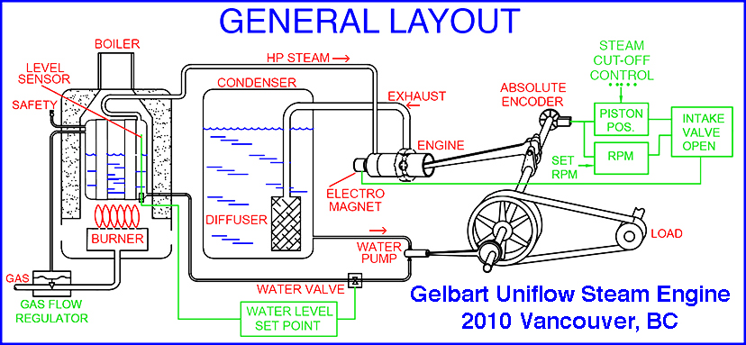
Electronic Controls:

An absolute shaft encoder measures the angle of crankshaft rotation; a control circuit (logic circuit or a microprocessor) derives the position of the piston in the cylinder, and also the engine RPM. When the piston reaches TDC, the intake valve is forced open by the piston; immediately thereafter, the control circuit activates the solenoid to keep the intake valve open to allow steam to enter the cylinder. When the control circuit switches off the current to the solenoid coil, the intake valve closes (steam cutoff). For example, as the load increases on the steam engine, the control circuit can hold the intake valve open for a longer period during the power stroke (letting in more steam), and thus maintain constant RPM. Other control modes for variable speed or power are possible.


Back to Top

Design Details:

Immega-Uniflow Constant Diameter Cylinder

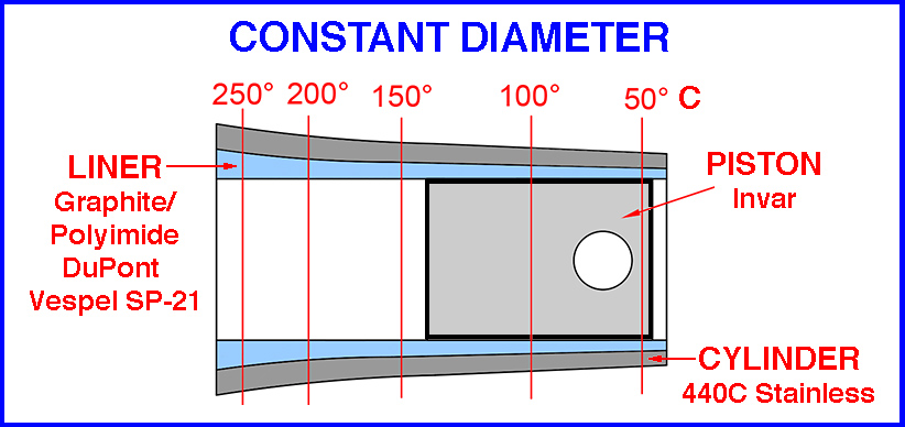
Constant Diameter Cylinder and Piston (The diameter change with temperature is highly exaggerated for clarity.)

The cylinder of a uniflow steam engine has large temperature gradient along its length, since – in order to maintain efficiency – it cannot be cooled (unlike a water-cooled IC engine). The hot end of the cylinder will have a larger diameter than the cooler exhaust end. However, an “athermalized” cylinder design (ID not effected by heat) can maintain good sealing of the piston at all cylinder temperatures.
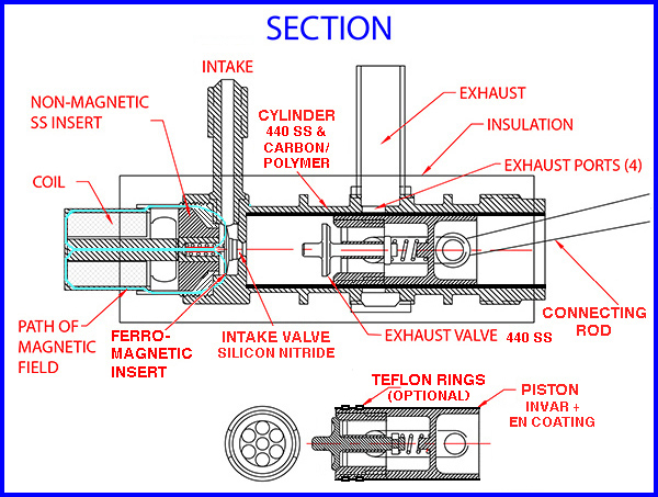
A constant diameter cylinder has an inner liner made of a material with a higher coefficient of thermal expansion (CTE) and a lower Young's modulus than outer cylinder material. When heated, the liner tries to expand faster than the cylinder body but it is constrained from doing so by the smaller CTE of the cylinder. Since the outer cylinder expands less, the liner material is compressed and the inside diameter (ID) remains constant. Thus, a temperature gradient along the cylinder will not change the ID. The liner material (carbon filled polyimide, DuPont Vespel SP-21) was selected for self-lubrication and very low wear against the hard materials used for the piston. The Vespel liner wall thickness should be about 7% of the liner OD (inserted in a 440 stainless cylinder) to maintain constant ID over a wide temperature range. The liner is cooled before insertion into the outer cylinder.
The piston is fabricated from Invar alloy, which has a near-zero CTE. The piston is plated with electroless nickel (EN) hard coating to achieve low wear. Depending on the materials selected for the cylinder liner and piston plating, Teflon piston rings may – or may not – be required.

No Lubrication

Superheated steam (250-300 degrees C) provides little lubrication for a piston moving in a cylinder. By carefully choosing compatible materials for the cylinder liner and the piston coating, an engine requiring no lubrication can be achieved. When the piston has a very good fit to the cylinder (at all temperatures) and has a large contact area with the cylinder, hydrodynamic lubrication can be achieved when the piston is in motion. Under such conditions, wear is minimal – allowing the use of steam with no oil or other lubrication.

Test Results

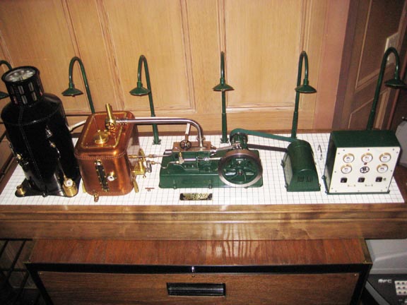
A scale model of the engine was built with a cylinder ID of 18 mm, stroke of 36 mm, working pressure of about 30 bar (435 PSI), and speed of up to 6000 RPM. The model was coupled to a small generator and was tested with an electrically heated boiler and atmospheric pressure condenser. Efficiency was measured as the ratio of the electrical power produced by the generator, corrected for generator efficiency, divided by the boiler net heating power (about 1KW, which was the limit of the test boiler). While it is difficult to achieve high efficiencies in a small-scale model, the demonstration engine achieved an efficiency of about 10%. At 40 bar (580 PSI) pressure, in burst mode with steam stored in the boiler, the engine produced over 300W.

Scalability

The advanced uniflow steam engine can be scaled to larger sizes using modern materials and designs. The electromagnetic cutoff for the intake valve (no valve gear) is a major improvement. A constant diameter cylinder can be made from cast iron with a low-friction carbon-polymer liner (which is also a good insulator). An Invar piston with a diamond-like coating (DLC) may be able to achieve low wear and a good seal without piston rings. The front surface of the exhaust valve in the piston should be plasma coated with zirconia to insulate it from the inlet steam. With a constant diameter cylinder and a precise fit for the piston, a bulky crosshead mechanism may not be needed.
For a large stationary engine, other designs may work best, while still using electromagnetic cutoff for the intake valve. The cylinder could be machined with a tapered bore, to approximate constant diameter when heated at one end. Both the cylinder and piston may be plasma coated with zirconia. Piston rings of polymer/graphite or pure graphite can provide lubrication and a good seal. A crosshead will eliminate side forces of the piston on the cylinder, reducing wear.


Back to Top

References:

  1. Curtis, N. (1901) "Engine" US Patent 671,394 Uniflow Steam Engine with Exhaust Valve in Piston
  2. Divine, W.J. (1975) "Uniflow Steam Engine" US Patent 3,910,160 Uniflow Steam Engine with Inlet and Exhaust Valves Operated by Piston
  3. Harvey, R. (1968) "Steam Engine with Self-Contained Valvular Mechanism" US Patent 3,361,036 Uniflow Steam Engine with Piston Operated Intake Valve and Exhaust Valves in Piston
  4. Kaneff, S. (1979-89) "The White Cliffs Solar Steam Engine" Australian Government Report on White Cliffs Solar Project
  5. Schoell, H. (2006) "Heat Regenerative Engine" US Patent 7,080,512 Uniflow Steam Engine that Uses Water as Both the Working Fluid and as the Lubricant
  6. Stumpf, Johann (1905) The Una-flow Steam Engine (Johann Stumpf (engineer))
  7. Sturtevant, H.V. (1968) "Steam Engine with Inlet Valve Mechanism" US Patent 3,397,619

External links:

  1. Dan's Uniflow Steam Engine (YouTube)
  2. Cyclone Uniflow Steam Engine
  3. Uniflow Steam Engine with Piston Operated Intake Valves

Back to Top